IO Setting
IO (Input/Output) ports on Elastel gateway is for connecting and communicating data with southbound devices which using IO interfaces, including ADC (Analog Input), DI (Digital Input), and DO (Digital Output).
IO setting is the configuration for Elastel gateway read/control data with south devices by IO interface.
Go to Data Collect >> South Devices>> IO to view and configure IO Settings.
ADC Setting
ADC (Analog-to-Digital Converter) is for converting analog input signals (continuous signals) into digital value (discrete signals), Elastel gateway (EG500 for example) provide 3xADC channels to connect with those analog signal type southbound devices, and convert AI data to digital value.

- Preview the current value that collected from southbound device under this rule communication
- Edit the added rule
- Delete the added rule
- Add a new rule
- Export and import the rules configuration in csv template file. This is useful for rules configuration backup and batch operation
Add an ADC setting rule
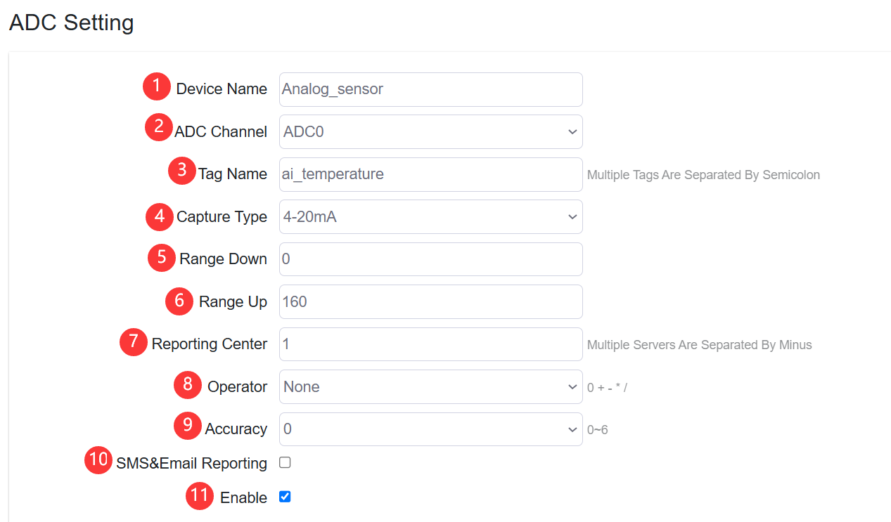
Click “Add” button to add a new ADC setting rule
-
Specify the southbound device name
-
Configure the ADC channel that southbound device connected for the rule applying.
NoteElastel Gateway EG500 provide 3xADC channels as ADC0, ADC1, ADC2
-
Configure the Tag Name of data converted from south device.
-
Configure the Analog input capture type, it supports 4~20mA, or 0~10V
-
Configure the range down value
-
Configure the range up value
Notethe ADC calculation formula is based on linear, take 4~20mA type as example, the K= (Range up-Range down)/(20mA-4mA). So the calculated Digital value= (Analog Current-4mA)*K
-
Specify the reporting center that the collected data be reported to. The number is associated to North App>>Reporting Server <1~5>
-
Configure the operator and operand
-
Configure the accuracy of calculated value
-
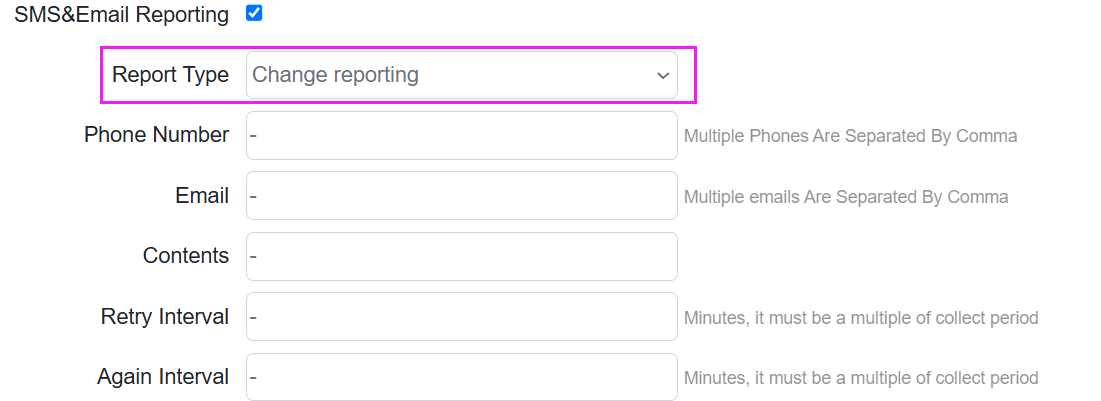
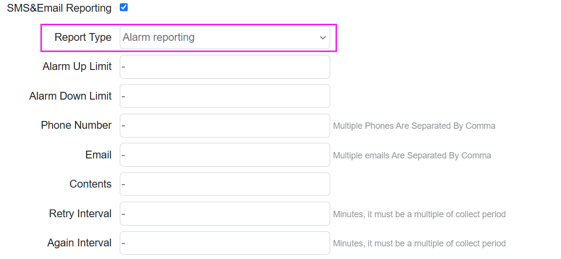
Enable/disable SMS&Email Reporting. It will send report to specified phone number and Email address when value changed or value out of certain range.
-
Enable/disable the rule be applied
DI Setting
DI (Digital Input) is a signal used to receive digital information from southbound devices, such as door sensor or switch, which can have two states: High (1) or Low (0). DI setting is used for detecting the DI device 1/0 (on/off) signals.

- Preview the current value that collected from southbound device under this rule communication
- Edit the added setting
- Delete the added setting
- Add a new setting
- Export and import the settings configuration in csv template file. This is useful for settings configuration backup and batch operation
Add a DI setting rule
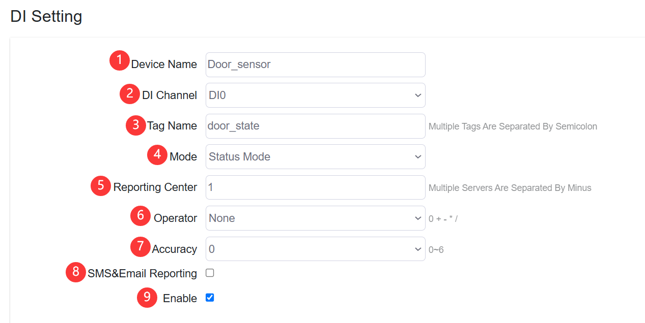
Click “Add” button to add a new DI setting rule
-
Specify the southbound device name
-
Configure the DI channel that southbound device connected for the rule applying.
NoteElastel Gateway EG500 provide 6xDI channels as DI0, DI1, DI2, DI3, DI4, DI5
-
Configure the Tag Name of data detected from south device.
-
Configure the DI calculation mode,
-
Status Mode, is for detecting the current states 0(low) or 1(high)
-
Counting Mode, is for counting the number of DI change in the collection period. Count Method for Configuring “Rising Edge” (0->1) or “Falling Edge” (1->0) as valid count Debounce Interval is Configuring for the interval to filter unusual DI signal.

-
-
Specify the reporting center that the collected data be reported to. The number is associated to North App>>Reporting Server <1~5>
-
Configure the operator and operand
-
Configure the accuracy of calculated value
-
Enable/disable SMS&Email Reporting. It will send report to specified phone number and Email address when value changed or value out of certain range.


-
Enable/disable the rule be applied
DO Setting
DO (Digital Output) is a signal used to Elastel gateway send digital output to southbound devices, such as relays, lights, or buzzer. It typically has two states: Clouse (1) or Open (0), to control the on/off status of connected southbound devices.

- Preview the current value that collected from southbound device under this rule communication
- Edit the added setting
- Delete the added setting
- Add a new setting
- Export and import the settings configuration in csv template file. This is useful for settings configuration backup and batch operation
Add a DO setting rule
Click “Add” button to add a new DO setting rule
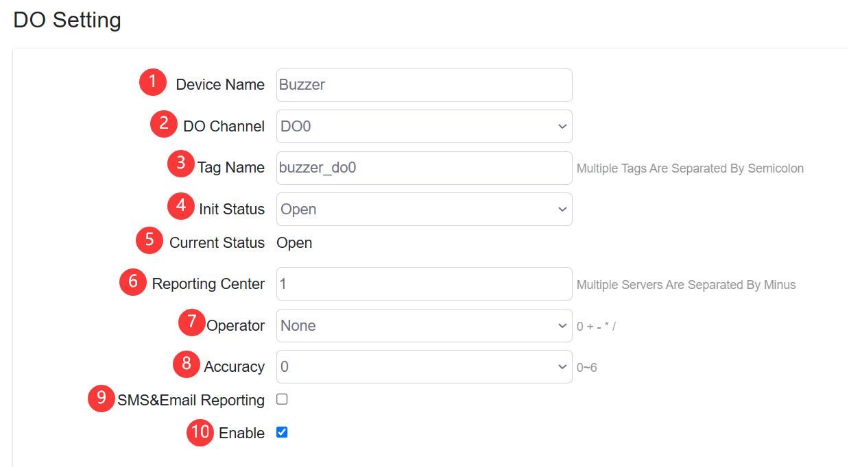
-
Specify the southbound device name
-
Configure the DO channel that southbound device connected for the rule applying.
NoteElastel Gateway EG500 provide 6xDO channels as DO0, DO1, DO2, DO3, DO4, DO5
-
Set the Tag Name of data detected from south device.
-
Set the Initial Status of DO, options Open, Close
-
Shows the current DO status
-
Specify the reporting center that the collected data be reported to. The number is associated to North App>>Reporting Server <1~5>
-
Set the operator and operand
-
Set the accuracy of calculated value
-
Enable/disable SMS&Email Reporting. It will send report to specified phone number and Email address when value changed or value out of certain range.


-
Enable/disable the rule be applied